39+ 5 Pin Din Connector Wiring Diagram PNG. After you have soldered the congratulations, you have successfully installed the 5 pin din male solder connector. I'm not concerned about the colours of the wires.
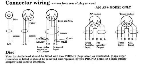
A&R A60 Din Pinouts | Flickr - Photo Sharing! from c2.staticflickr.com Then i'll write down which din pin corresponds to which cartridge pin. Please consult any wiring information you have available to determine which conductors should be wired to each pin. Some of these connectors have also been used in analog video applications and digital interfaces.
This page not supported any more.
After you have soldered the congratulations, you have successfully installed the 5 pin din male solder connector. I'm not concerned about the colours of the wires. My male adapter 2 pins on left side, a small rectangle in the middle, and 3. There are three different signalling methods which have historically been used on pc keyboards.
Share this post
0 Response to "5 Pin Din Connector Wiring Diagram"

0 Response to "5 Pin Din Connector Wiring Diagram"
Post a Comment