Diagrams Of Single Phase Motors
Get Diagrams Of Single Phase Motors Gif. The single phase motor are those motor which is working one phase and neutral (ground) supply for doing his duty and a 3 phase motor required 3 phase power source. The above diagram is a complete method of single phase motor wiring with circuit breaker and contactor.
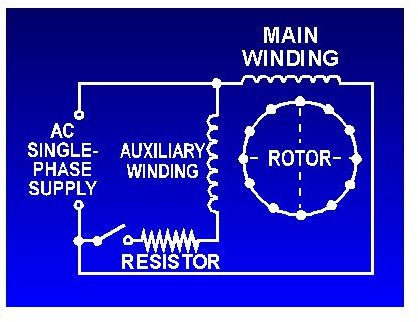
Electronic starter for single phase motor is used for protecting motor from over currents and different starter methods are discussed in brief.
Electronic starter for single phase motor is used for protecting motor from over currents and different starter methods are discussed in brief. This diagram illustrates possible wiring using a tesys d (lc1d****) contactor and tesys. Once the motor is spinning and has inertia, a centrifugal switch opens and the capacitor network is disconnected from the primary motor windings. The speed at which the switch opens happens before reaching the.

0 Response to "Diagrams Of Single Phase Motors"
Post a Comment